
Introduction
In the majority of glass plant installations, vessels find universal applications as reactors,re-boilers, receivers and separators as well as for storage, feed or measuring.
Vessels are available in spherical & cylindrical shape form 5 to 500 liter capacity. All vessels are provided with bottom outlet nozzle for which a suitable valve can be selected form the range of valves. Both spherical and cylindrical vessels can be supplied with graduation to special order.
Cylindrical vessel can be supplied with glass / metal jacket also.
Vessels & Stirrers
| Nominal Cap. Ltr. | Bulb Cap. Ltr. | Working Cap. Ltr. | Maximum Internal Pressure (bar G.) |
|---|---|---|---|
| 5L | 5L | 4L | 1.0 |
| 10L | 10L | 9L | 0.8 |
| 20L | 21L | 20L | 0.7 |
| 50L | 62L | 58L | 0.5 |
| 100L | 118L | 111L | 0.4 |
| 200L | 212L | 200L | 0.25 |
| 300L | 315L | 300L | 0.2 |
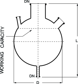
| Nominal Cap. Ltr. | Bulb Diameter in MM (D) | Vessel Length in MM (L) | Tolerance in Diameter mm | Tolerance in Length mm L |
|---|---|---|---|---|
| 5L | 223 | 425 | ±2 | ±5 |
| 10L | 285 | 500 | ±2 | ±5 |
| 20L | 350 | 575 | ±2 | ±5 |
| 50L | 490 | 800 | ±3 | ±5 |
| 100L | 600 | 900 | ±5 | ±10 |
| 200L | 750 | 1100 | ±5 | ±15 |
| 300L | 860 | 1175 | ±6 | ±15 |

| Nominal Cap. Ltr | DN mm | L mm |
|---|---|---|
| 5L | 50 | 300 |
| 10L | 80 | 375 |
| 20L | 100 | 450 |
| 50L | 150 | 600 |
| 100L | 225 | 700 |
| 200L | 300 | 900 |
| 300L | 400 | 1000 |

| Nominal Cap. Ltr | DN mm | DN1 mm | DN2 mm | L mm |
|---|---|---|---|---|
| 5L | 50 | 25 | 25 | 425 |
| 10L | 80 | 25 | 25 | 500 |
| 20L | 100 | 25 | 25 | 575 |
| 50L | 150 | 40 | 40 | 800 |
| 100L | 225 | 40 | 40 | 900 |
| 200L | 300 | 40 | 40 | 1100 |
| 300L | 400 | 50 | 50 | 1175 |

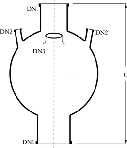
| Nominal Cap. Ltr | DN mm | DN1 mm | DN2 mm | DN3 mm | L mm |
|---|---|---|---|---|---|
| 5L | 50 | 25 | 25 | 40 | 425 |
| 10L | 80 | 25 | 25 | 40 | 500 |
| 20L | 100 | 25 | 25 | 40 | 575 |
| 50L | 150 | 40 | 40 | 100 | 800 |
| 100L | 225 | 40 | 40 | 100 | 900 |
| 200L | 300 | 40 | 40 | 100 | 1100 |
| 300L | 400 | 50 | 50 | 100 | 1175 |
This vessel is used in circulatory boiler systems. Additional nozzles can be provided on the equator on request for special requirement .

| Nominal Cap. Ltr | DN mm | DN1 mm | DN2 mm | DN3 mm | L mm |
|---|---|---|---|---|---|
| 5L | 50 | 25 | 25 | 50 | 425 |
| 10L | 80 | 25 | 25 | 50 | 500 |
| 20L | 100 | 25 | 25 | 50 | 575 |
| 50L | 150 | 40 | 40 | 80 | 800 |
| 100L | 225 | 40 | 40 | 80 | 900 |
| 200L | 300 | 40 | 40 | 100 | 1100 |
| 300L | 400 | 50 | 50 | 150 | 1175 |
Receiver is provided with built in dip pipe. This is to be supported on a vessel holding ring.

| Nominal Cap. Ltr | DN mm | DN1 mm | DN2 45° | DN3 45° | L mm |
|---|---|---|---|---|---|
| 5L | 25 | 25 | 25 | - | 350 |
| 10L | 25 | 25 | 25 | - | 425 |
| 20L | 25 | 25 | 25 | - | 500 |
| 5L | 25 | 25 | 25 | 25 | 350 |
| 10L | 25 | 25 | 25 | 25 | 425 |
| 20L | 25 | 25 | 25 | 25 | 500 |
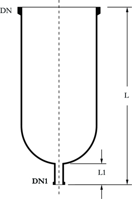
This vessel is provided with a short bottom outlet , it should be supported on vessel holder /holding ring.

| Nominal Cap. Ltr | DN mm | DN1 mm | L mm |
|---|---|---|---|
| 5L | 50 | 25 | 375 |
| 10L | 80 | 25 | 435 |
| 20L | 100 | 25 | 510 |
| 50L | 150 | 40 | 675 |
| 100L | 225 | 40 | 775 |
| 200L | 300 | 40 | 975 |
| 300L | 400 | 50 | 1075 |
This vessel is used to fit immersion heat exchanger at the bottom.
| Nominal Cap. Ltr | DN mm | DN1 mm | DN2 mm | DN3 mm | L mm |
|---|---|---|---|---|---|
| 50L | 150 | 150 | 40 | 100 | 800 |
| 100L | 225 | 150 | 40 | 100 | 900 |
| 200L | 300 | 150 | 40 | 100 | 1150 |
| 50L | 150 | 225 | 40 | 100 | 825 |
| 100L | 225 | 225 | 40 | 100 | 950 |
| 200L | 300 | 225 | 40 | 100 | 1200 |
Cyclone is used for the separation of droplets and solids from gases and vapours. Cyclone is supported on a vessel holder. A dip pipe is used on the top neck.

| Nominal Cap. Ltr | DN mm | DN1 mm | DN2 mm | DN3 mm | L mm |
|---|---|---|---|---|---|
| 5L | 50 | 25 | 25 | 40 | 425 |
| 10L | 80 | 25 | 25 | 40 | 500 |
| 20L | 100 | 25 | 25 | 50 | 575 |
| 50L | 150 | 40 | 40 | 50 | 800 |

To fit a bottom outlet valve (BAL type) all spherical and cylindrical vessel can be supplied with valve seat in bottom outlet.
Cylindrical vessels can be used for various applications such as reaction, separating receiver,feeding etc. 50 liter and above cylindrical vessels need to be supported in a vessel holder.
| Nominal Cap. Ltr | DN mm | DN1 mm | L MM | L1 MM | CAT.REF. |
|---|---|---|---|---|---|
| 5L | 100 | 25 | 700 | 60 | HVZ5/4 |
| 5L | 150 | 25 | 460 | 60 | HVZ5/6 |
| 10L | 150 | 25 | 700 | 60 | HVZ10/6 |
| 20L | 225 | 25 | 750 | 60 | HVZ20/9 |
| 30L | 300 | 40 | 650 | 60 | HVZ30/12 |
| 50L | 300 | 40 | 915 | 65 | HVZ50/12 |
| 100L | 450 | 40 | 900 | 65 | HVZ100/18 |
| 150L | 450 | 40 | 1200 | 65 | HVZ150/16 |
| 200L | 450 | 40 | 1500 | 65 | HVZ200/18 |
| 300L | 600 | 50 | 1300 | 65 | HVZ300/24 |
| 400L | 600 | 50 | 1650 | 65 | HVZ300/24 |
If need the graduation marking on the vessel, please mention the "G" with catalogue code.The same vessel can be supplied in reduced top neck.

| Nominal Cap. Ltr | DN mm | DN1 mm | DN2 mm | L mm | CAT.REF. |
|---|---|---|---|---|---|
| 5L | 100 | - | 2 x 25 | 200 | HVZA5/4 |
| 5L | 150 | - | 2 x 25 | 200 | HVZA5/6 |
| 10L | 150 | 50 | 2 x 25 | 200 | HVZA10/6 |
| 20L | 225 | 50 | 3 x 25 | 250 | HVZA20/9 |
| 30L | 300 | 50 | 3 x 25 | 250 | HVZA30/12 |
| 50L | 300 | 50 | 3 x 40 | 250 | HVZA50/12 |
| 300 | 80 | 3 x 50 | 250 | ||
| 100L | 450 | 50 | 3 x 40 | 275 | HVZA100/18 |
| 450 | 80 | 3 x 40 | 275 | ||
| 450 | 100 | 3 x 40 | 275 | ||
| 150L | 400 | 100 | 3 x 40 | 275 | HVZA150/16 |
| 200L | 450 | 100 | 3 x 40 | 275 | HVZA200/18 |
| 300L | 600 | 50 | 3 x 40 | 300 | HVZA300/24 |
| 600 | 80 | 4 x 40 | 300 | ||
| 600 | 100 | 4 x 40 | 300 | ||
| 400L | 600 | 100 | 4 x 40 | 300 | HVZA400/24 |

| Nominal Cap. Ltr | D mm | DN mm | DN1 mm | L mm | L1 mm | CAT.REF. |
|---|---|---|---|---|---|---|
| 20L | 300 | 100 | 25 | 650 | 60 | HVZR20/12 |
| 30L | 300 | 150 | 25 | 800 | 65 | HVZR30/12 |
| 50L | 300 | 150 | 40 | 1000 | 65 | HVZR50/12 |
| 100L | 450 | 225 | 40 | 1100 | 65 | HVZR100/18 |
| 150L | 450 | 225 | 40 | 1400 | 65 | HVZR150/16 |
| 200L | 450 | 225 | 40 | 1625 | 65 | HVZR200/18 |
| 300L | 600 | 225 | 40 | 1500 | 75 | HVZR300/24 |
| 400L | 600 | 300 | 40 | 1715 | 75 | HVZR400/24 |

| Nominal Cap. Ltr | D mm | DN mm | DN1 mm | L mm | L1 mm | CAT.REF. |
|---|---|---|---|---|---|---|
| 5L | 200 | 50 | 25 | 40 | 475 | HVCY5 |
| 10L | 220 | 50 | 25 | 40 | 600 | HVCY10 |
| 20L | 300 | 80 | 25 | 50 | 650 | HVCY20 |
| 30L | 300 | 80 | 25 | 50 | 790 | HVCY30 |
| 50L | 420 | 100 | 40 | 100 | 795 | HVCY50 |
| 100L | 470 | 150 | 40 | 100 | 1020 | HVCY100 |
| 150L | 470 | 150 | 40 | 100 | 1315 | HVCY150 |
| 200L | 600 | 225 | 40 | 100 | 1190 | HVCY200 |
| 300L | 600 | 225 | 40 | 100 | 1590 | HVCY300 |
| 400L | 600 | 300 | 40 | 100 | 1715 | HVCY400 |

| Nominal Cap. Ltr | D mm | DN mm | DN1 mm | L mm | L1 mm | CAT.REF. |
|---|---|---|---|---|---|---|
| 10L | 215 | 40 | 25 | 410 | 100 | HAB10 |
| 20L | 280 | 40 | 25 | 485 | 100 | HAB20 |
For special applications, cylindrical vessels can be supplied with a jacket for heating or cooling. Jacket is sealed to the vessel with silicon rubber or viton '0' ring and other sealing compositions. The seal prevents impermissible high stresses between vessel and jacket and allows the movement which comes due to thermal expansion.

| Nominal Cap. Ltr | DN mm | DN1 mm | DN2 mm | D mm | L mm | L1 mm | CAT.REF. |
|---|---|---|---|---|---|---|---|
| 5L | 100 | 25 | 25 | 165 | 825 | 150 | HVZD5/4 |
| 150 | 25 | 25 | 220 | 600 | 150 | HVZD5/6 | |
| 10L | 150 | 25 | 25 | 220 | 850 | 150 | HVZD10/6 |
| 225 | 40 | 25 | 300 | 600 | 175 | HVZD10/9 | |
| 20L | 225 | 40 | 25 | 300 | 900 | 200 | HVZD20/9 |
| 300 | 40 | 25 | 390 | 650 | 200 | HVZD20/12 | |
| 30L | 300 | 40 | 25 | 390 | 775 | 200 | HVZD30/12 |
| 50L | 300 | 40 | 25 | 390 | 1050 | 200 | HVZD50/12 |
| 60L | 300 | 40 | 25 | 390 | 1200 | 200 | HVZD60/12 |
| 100L | 400 | 40 | 25 | 460 | 1100 | 210 | HVZD100/16 |
| 450 | 40 | 25 | 515 | 1000 | 210 | HVZD100/18 |
This vessel can also be supplied with metal jacket. Metal Jacket can be used in a maximum O operating pressure of 2.0 bar g and a maximum operation temperature of 150 C.
Temperature difference between jacket & vessel should not exceed 120C.
Vessel holders is made of cast aluminium with a plaster lining shape to fit the vessel . Vessel holder is fitted with 3 jacking bolts

| Vessel holder size wise | D mm | d mm | L mm | CAT.REF. |
|---|---|---|---|---|
| 20L | 325 | 230 | 100 | HVSS20 |
| 30L | 325 | 230 | 100 | HVSS30 |
| 50L | 390 | 230 | 100 | HVSS50 |
| 100L | 420 | 250 | 100 | HVSS100 |
| 200L | 700 | 400 | 215 | HVSS200 |

| Vessel holder size wise | D mm | L mm | CAT.REF. |
|---|---|---|---|
| 2L | 100 | 15 | HVRS 2 |
| 5L | 150 | 15 | HVRS 5 |
| 10L | 215 | 15 | HVRS 10 |
| 20L | 300 | 15 | HVRS 20 |
Dip pipe is used as liquid inlet for spherical & cylindrical vessels.

| Nominal Cap. Ltr | DN mm | DN1 mm | d mm | L mm | L1 mm | CAT.REF. |
|---|---|---|---|---|---|---|
| 20L | 25 | 25 | 12 | 300 | 100 | HDP20/1 |
| 50L | 40 | 25 | 19 | 400 | 100 | HDP50/1.5 |
| 100L | 40 | 25 | 19 | 500 | 100 | HDP100/1.5 |
| 200L | 40 | 25 | 19 | 600 | 100 | HDP200/1.5 |
Short dip pipe is used as re–entry tube for vessel, heat exchanger etc.
| Nominal Cap. Ltr | DN mm | DN1 mm | d mm | L mm | L1 mm | CAT.REF. |
|---|---|---|---|---|---|---|
| 20L | 25 | 25 | 12 | 300 | 100 | HDP20/1 |
| 50L | 40 | 25 | 19 | 400 | 100 | HDP50/1.5 |
| 100L | 40 | 25 | 19 | 500 | 100 | HDP100/1.5 |
| 200L | 40 | 25 | 19 | 600 | 100 | HDP200/1.5 |
Gas sparger is used for gas feeding & sparging in vessels.

| Nominal Cap. Ltr | DN mm | DN1 mm | d mm | L mm | L1 mm | No. of Holes | CAT.REF. |
|---|---|---|---|---|---|---|---|
| 20L | 25 | 25 | 12 | 300 | 100 | 5 x 1mm | HGS20/1 |
| 50L | 40 | 25 | 19 | 400 | 100 | 5 x 1mm | HGS20/1.5 |
| 100L | 40 | 25 | 19 | 500 | 100 | 5 x 1mm | HGS100/1.5 |
| 200L | 40 | 25 | 19 | 600 | 100 | 5 x 1mm | HGS200/1.5 |
Thermometer pocket is used to put thermometer , where temperature need to be measured.

| Nominal Cap. Ltr | DN mm | d mm | L mm | L1 mm | CAT.REF. |
|---|---|---|---|---|---|
| 5L | 25 | 12 | 150 | 50 | HTP5/1 |
| 10L | 25 | 12 | 200 | 50 | HTP10/1 |
| 20L | 25 | 12 | 300 | 50 | HTP20/1 |
| 50L | 40 | 19 | 400 | 50 | HTP50/1.5 |
| 100L | 40 | 19 | 500 | 50 | HTP100/1.5 |
| 200L | 40 | 19 | 600 | 50 | HTP200/1.5 |
| 300L | 40 | 19 | 680 | 50 | HTP300/1.5 |
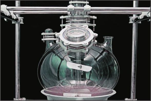
A variety of stirrers and stirrer drives are available to use glass vessel as agitated reaction equipments. Stirrer assemblies are used with spherical or cylindrical vessels and generally comprise two main components: a drive unit (including shaft seal) and a stirrer shaft.In addition a reducer or vessels cover is normally required, to connect the top neck of the vessel to the drive unit. Variable speed drive unit can be supplied on request.
This unit is suitable for use under corrosive conditions. Only GLASS & PTFE are exposed to process fluids. Bellow seal can be used under vacuum down to 10mm Hg absolute.Mechanical seal can be used under vacuum1 mm Hg absolute or under pressure permitted into glass vessels

| Vessel Cap. Ltr | DN mm | D mm | CAT. REF. BELLOW SEAL | CAT. REF.MECH. SEAL |
|---|---|---|---|---|
| 10L | 50 | 24.5 | HCSA1 | HCSM1 |
| 20L | 50 | 24.5 | HCSA1 | HCSM1 |
| 50L | 50 | 24.5 | HCSA1 | HCSM1 |
| 100L | 50 | 45.5 | HCSA1.5 | HCSM1.5 |
| 200L | 50 | 45.5 | HCSA1.5 | HCSM1.5 |
| 300L | 50 | 45.5 | HCSA1.5 | HCSM1.5 |
This stirrer is used for low viscosity fluid.
| Vessel Cap. Ltr | d mm | D mm | L | L1 | L2 | CAT. REF.MECH. SEAL |
|---|---|---|---|---|---|---|
| 5L | 24.5 | 40 | 625 | 350 | 25 | HSTB5 |
| 10L | 24.5 | 40 | 700 | 350 | 25 | HSTB10 |
| 20L | 24.5 | 70 | 800 | 350 | 25 | HSTB20 |
| 50L | 24.5 | 100 | 1000 | 350 | 25 | HSTB50 |
| 100L | 45.5 | 150 | 1200 | 400 | 30 | HSTB100 |
| 200L | 45.5 | 175 | 1400 | 400 | 30 | HSTB200 |
| 300L | 45.5 | 200 | 1500 | 400 | 30 | HSTB300 |
This stirrer is used for low viscosity fluid containing small solid particles.

| Vessel Cap. Ltr | d mm | D mm | L | L1 | L2 | CAT. REF.MECH. SEAL |
|---|---|---|---|---|---|---|
| 5L | 24.5 | 40 | 625 | 350 | 50 | HSTV5 |
| 10L | 24.5 | 40 | 700 | 350 | 50 | HSTV100 |
| 20L | 24.5 | 50 | 800 | 350 | 50 | HSTV20 |
| 50L | 24.5 | 65 | 1000 | 350 | 65 | HSTV50 |
| 100L | 45.5 | 65 | 1200 | 400 | 65 | HSTV100 |
| 200L | 45.5 | 105 | 1400 | 400 | 65 | HSTV200 |
| 300L | 45.5 | 105 | 1500 | 400 | 65 | HSTV300 |
This stirrer is used for high viscosity fluid containing big solid particles.

| Vessel Cap. Ltr | d mm | D mm | L | L1 | L2 | CAT. REF.MECH. SEAL |
|---|---|---|---|---|---|---|
| 5L | 24.5 | 40 | 625 | 350 | 50 | HSTP5 |
| 10L | 24.5 | 40 | 700 | 350 | 50 | HSTP10 |
| 20L | 24.5 | 50 | 800 | 350 | 50 | HSTP20 |
| 50L | 24.5 | 65 | 1000 | 350 | 65 | HSTP50 |
| 100L | 24.5 | 65 | 1200 | 400 | 65 | HSTP100 |
| 200L | 45.5 | 105 | 1400 | 400 | 65 | HSTP200 |
| 300L | 45.5 | 105 | 1500 | 400 | 65 | HSTP300 |
This stirrer produces axial primary flow with a radial component and is particularly suitable for homogenisation and suspension. It is also suitable for general stirring duties with simultaneous heat transfer (heating or cooling) between the liquid being stirred and the vessel wall. It can also be used for dispersion (including from gases) and emulsification.This stirrer is available in three combinations (like Propeller /TurbineAnchor type).

| L | d | D | Cat. Ref |
|---|---|---|---|
| 700 | 45 | 150 | HSPT150/700 |
| 800 | 45 | 150 | HSPT150/800 |
| 800 | 45 | 150 | HSPT150/800 |
| 1100 | 45 | 150 | HSPT150/1100 |
| 1350 | 45 | 200 | HSPT200/1350 |
A stirrer is assembled in chuck with bellow seal and appropriate reducer. This assembly is convenient to install on a vessel . This assembly mainly consists of :
- Glass Stirrer (HSTB/ HSTV/ HSTP )
- Chuck and seal (HSCA)
- Glass Reducer (HPR)

| Vessel Cap. Ltr. | Stripper Used | Chuck & Seal Used | Reducer Used | CAT.REF. |
|---|---|---|---|---|
| 10L | HSTB10 | HCSA1 | HSTBA10 | |
| 20L | HSTB20 | HCSA1 | HPR3/2 | HSTBA20 |
| 50L | HSTB50 | HCSA1 | HPR4/2 | HSTBA50 |
| 100L | HSTB100 | HCSA1.5 | HPR6/3 | HSTBA100 |
| 200L | HSTB200 | HCSA1.5 | HPR9/3 | HSTBA200 |
| 300L | HSTB300 | HCSA1.5 | HPR12/3 | HSTBA300 |
| 10L | HSTV10 | HCSA1 | - | HSTVA10 |
| 20L | HSTV20 | HCSA1 | HPR3/2 | HSTVA20 |
| 50L | HSTV50 | HCSA1 | HPR4/2 | HSTVA50 |
| 100L | HSTV100 | HCSA1.5 | HPR6/3 | HSTVA100 |
| 200L | HSTV200 | HCSA1.5 | HPR9/3 | HSTVA200 |
| 300L | HSTV300 | HCSA1.5 | HPR12/3 | HSTVA300 |
| 10L | HSTV10 | HCSA1 | - | HSTPA10 |
| 20L | HSTP20 | HCSA1 | HPR3/2 | HSTPA20 |
| 50L | HSTP50 | HCSA1 | HPR4/2 | HSTPA50 |
| 100L | HSTP100 | HCSA1.5 | HPR6/3 | HSTPA100 |
| 200L | HSTP200 | HCSA1.5 | HPR9/3 | HSTPA200 |
| 300L | HSTP300 | HCSA1.5 | HPR12/3 | HSTPA300 |
| 300L | HSTP300 | HCSA1.5 | HPR12/3 | HSTPA300 |
A stirrer is assembled in chuck with mechanical seal and appropriate reducer. This assembly is convenient to install on a vessel .
- Glass Stirrer (HSTB/ HSTV/ HSTP )
- Chuck and seal (HSCA)
- Glass Reducer (HPR)

| Vessel Cap. Ltr. | Stripper Used | Chuck & Seal Used | Reducer Used | CAT.REF. |
|---|---|---|---|---|
| 10L | HSTB10 | HCSA1 | - | HSTBM10 |
| 20L | HSTB20 | HCSA1 | HPR3/2 | HSTBM20 |
| 50L | HSTB50 | HCSA1 | HPR4/2 | HSTBM50 |
| 100L | HSTB100 | HCSA1.5 | HPR6/3 | HSTBM100 |
| 200L | HSTB200 | HCSA1.5 | HPR9/3 | HSTBM200 |
| 300L | HSTB300 | HCSA1.5 | HPR12/3 | HSTBM300 |
| 10L | HSTB10 | HCSA1 | - | HSTVM10 |
| 20L | HSTV20 | HCSA1 | HPR3/2 | HSTVM20 |
| 50L | HSTV50 | HCSA1 | HPR4/2 | HSTVM50 |
| 100L | HSTV100 | HCSA1.5 | HPR6/3 | HSTVM100 |
| 200L | HSTV200 | HCSA1.5 | HPR9/3 | HSTVM200 |
| 300L | HSTV300 | HCSA1.5 | HPR12/3 | HSTVM300 |
| 10L | HSTP10 | HCSA1 | - | HSTPM10 |
| 20L | HSTP20 | HCSA1 | HPR3/2 | HSTPM20 |
| 50L | HSTP20 | HCSA1 | HPR4/2 | HSTPM50 |
| 100L | HSTP100 | HCSA1.5 | HPR6/3 | HSTPM100 |
| 200L | HSTP200 | HCSA1.5 | HPR9/3 | HSTPM200 |
| 300L | HSTP300 | HCSA1.5 | HPR12/3 | HSTPM300 |
A 1400 RPM 3 Phase non-flameproof motor with built-in gear is supplied along with a flexible shaft. A motor coupling to couple the flexible shaft to motor is also provided. Other end of the flexible shaft is to be fitted into the chuck.

| HP | SPEED RPM | CAT.REF. |
|---|---|---|
| 0.25 | 190 | HRSD 0.25 |
| 0.5 | 195 | HRSD 0.5 |
| 1.0 | 195 | HRSD 1 |
This motor is also available in FLAME PROOF
3 Phase non-flame proof regulators are available to control the speed of stirrer drives.

| Type | Phase | CAT.REF. |
|---|---|---|
| 0.25 | 190 | HFSD0.25 |
| 0.5 | 195 | HFSD0.5 |
| 1.0 | 195 | HFSD 1 |
M. S. Heating bath is used for electrical or steam heating of glass vessels. Depending upon the temperature requirements, different types of thermic fluids oil or water can be used as heating media. Heating bath is provided with a pair of NON flame proof heaters with digital controller box, M.S coil for passing the steam or cooling water, cushioned vessel holding ring, a bottom outlet sealing arrangement, a lid and threaded socket type inlets and outlets

| Vessel Cap. Ltr. | D mm | L mm | POWER(kW) | CAT.REF. |
|---|---|---|---|---|
| 5L | 325 | 225 | 2 kW ( 2 x 1000) | HBH5 |
| 10L | 350 | 250 | 2 kW ( 2 x 1000) | HBH10 |
| 20L | 480 | 340 | 3 kW ( 3 x 1500) | HBH20 |
| 50L | 615 | 415 | 4 kW ( 2 x 2000) | HBH50 |
| 100L | 720 | 535 | 6 kW ( 2 x 3000) | HBH100 |
| 200L | 900 | 620 | 8 kW ( 2 x 4000) | HBH200 |
M.S. Jacketed Heating bath is provided with a coil inside to circulate either steam or heat transfer fluid depending upon the application . Provision for placing a electrical heater is also kept.
(Non Flame proof )- Heater can also be provided along with the bath on request . Although the standard heating bath is specifically designed for spherical vessel , similar bath for cylindrical vessel can also be supplied on special order. This heating bath can be fitted with suitable temperature control equipments if required.

| Vessel Cap. Ltr. | D mm | L mm | POWER(kW) | CAT.REF. |
|---|---|---|---|---|
| 5L | 395 | 260 | 2 kW ( 2 x 1000) | HBHD5 |
| 10L | 420 | 285 | 2 kW ( 2 x 1000) | HBHD10 |
| 20L | 550 | 365 | 3 kW ( 3 x 1500) | HBHD20 |
| 50L | 685 | 465 | 4 kW ( 2 x 2000) | HBHD50 |
| 100L | 830 | 560 | 6 kW ( 2 x 3000) | HBHD100 |
| 200L | 1050 | 680 | 8 kW ( 2 x 4000) | HBHD200 |
* S.S. Heating bath can be supplied on request . This should be specified during inquiry stage.
* S.S. / Copper coil can be supplied on request . This should be specified during inquiry stage.
Cooling bath is used for cooling the glass vessel with ice crystals. Cooling bath is provided with cushioned vessel holding ring, a bottom outlet sealing arrangement and a lid.

| Vessel Cap. Ltr. | D mm | L mm | CAT.REF. |
|---|---|---|---|
| 5L | 325 | 225 | HBHC5 |
| 10L | 350 | 250 | HBHC10 |
| 20L | 480 | 330 | HBHC20 |
| 50L | 615 | 415 | HBHC50 |
| 100L | 720 | 535 | HBHC100 |
| 200L | 900 | 620 | HBHC200 |
As an alternative to heating bath, electric heating mantle can also be supplied for spherical & cylindrical vessels. It’s heating power varies according to the nominal capacity of the vessel involved.
This heating mantle is sub-divided into several heating zones each of which is equipped with a temperature probe so that the surface temperature of the vessel can be monitored.This work in conjunction with the control unit includes in the supply to prevent local hot spots occurring. The control unit also includes energy regulators , which can be used to control the heat input separately for each heating zone depending on the liquid leve

| Vessel Cap. Ltr. | D mm | L mm | ELEC.SUPPLY | CIRCUTS | POWER (kW) | CAT.REF. |
|---|---|---|---|---|---|---|
| 5L | - | 260 | 230V | 1 | 0.6 kW ( 1 x 600) | HJMD5 |
| 10L | - | 285 | 230V | 3 | 1.0 kW ( 2 x 500) | HJMD10 |
| 20L | 550 | 365 | 230V | 3 | 1.5 kW ( 3 x 500) | HJMD20 |
| 50L | 685 | 465 | 440V | 3 | 3.6 kW ( 4 x 900) | HJMD50 |
| 100L | 830 | 560 | 440V | 3 | 5.4 kW ( 6 x 900) | HJMD100 |
| 200L | 1050 | 680 | 440V | 6 | 8.0 kW ( 8 x 1000) | HJMD200 |
Powder coating / S.S. Heating bath can be supplied on request . This should be specified during inquiry stage.
S.S. / Copper coil can be supplied on request . This should be specified during inquiry stage.
In all cases , electrical supply should be specified when ordering . All heating mantles are non-flame proof type. Flame proof heating mantle can be supplied on request.

Decantation is a process of separation of two immiscible liquids, having different densities.When these liquids are allowed to settle, two distinct layers are formed, heavier at bottom and lighter at top. This is a decantor which is suitable for continuous decantation .The mixture of liquids is continuously feed in the decantor at low velocity. This allows sufficient residence time for the formation of separate layers. The light phase liquid is continuously removed from the light phase outlet at the top. The heavy phase liquid enters the dip pipe at lower and overflow in the discharge pipe and is removed from the bottom.
This decantor provides continuous separation, visual monitoring, and ensures separation even after feeding is stopped. Decantor can be provided with adjustable overflow valve,(Type B) to adjust the position of interface for different operating situations

| Nom.Cap. | DN | DN1 | DN2 | DN3 | DN4 | DN5 | DN6 | DN7 | L | L1 | L2 | L3 | L4 | TYPE | CAT REF. |
|---|---|---|---|---|---|---|---|---|---|---|---|---|---|---|---|
| 20L | 80 | 25 | 50 | 25 | 25 | 25 | 25 | 50 | 800 | 125 | 525 | 150 | - | A | HSPS20 |
| 50L | 100 | 40 | 50 | 25 | 25 | 40 | 40 | 50 | 1025 | 150 | 725 | 150 | - | A | HSPS50 |
| 100L | 150 | 40 | 50 | 25 | 25 | 40 | 40 | 50 | 1175 | 200 | 825 | 150 | - | A | HSPS100 |
| 200L | 225 | 40 | 50 | 25 | 25 | 40 | 40 | 50 | 1475 | 250 | 1075 | 150 | - | A | HSPS200 |
| 20L | 80 | 25 | 50 | 25 | 25 | 25 | 25 | 50 | 1000 | 125 | 525 | 150 | 200 | B | HSPA20 |
| 50L | 100 | 40 | 50 | 25 | 25 | 40 | 40 | 50 | 1225 | 150 | 725 | 150 | 200 | B | HSPA50 |
| 100L | 150 | 40 | 50 | 25 | 25 | 40 | 40 | 50 | 1375 | 200 | 825 | 150 | 200 | B | HSPA100 |
| 200L | 225 | 40 | 50 | 25 | 25 | 40 | 40 | 50 | 1675 | 250 | 1075 | 150 | 200 | B | HSPA200 |
Decantor can be constructed with horizontal cylindrical vessels and to provide larger separating surfac


